 ¿Está buscando una aplicación para ingeniería que resuelva los problemas de diseño , reduzca errores y ahorre costes, rediseñe más rápidamente, y trabajar con su sistema CAD 3D o como una aplicación independiente ?
SimWise 4D está desarrollado para profesionales de la ingeniería y el diseño que desarrollan productos, ensamblajes, formados por conjuntos de piezas en 3D. Mediante la simulación de sus ensamblajes en este entorno virtual único , usted producirá diseños robustos, más creativos y reducir el tiempo de desarrollo.
Con SimWise 4D , puede simular la dinámica del sólido rígido de ensamblajes, componentes de dimensiones, determinar interferencias y colisiones, identificar las tensiones inducidas por el movimiento, generar animaciones basados en la física y poner a prueba sus sistemas de control.
Una Herramienta de Simulación muy Probada
SimWise 4D nació cuando DST adquirió una licencia de MSC Software Corporation del producto MSC.visualNastran 4D ( vn4D ) . El software tiene sus raíces en el software Working Model 3D desarrollado por Knowledge Revolution, que fue adquirida por MSC en 1999 , se amplió para incluir capacidades de FEA y fue renombrado a Working Model 4D . Hay decenas de miles de usuarios entre profesionales de la ingeniería , estudiantes y personal académico.
SimWise 4D está formado por SimWise Motion y SimWise FEA. SimWise Motion, está enfocado a simulación de movimiento cinemático y dinámico en 3D. SimWise FEA permite análisis estáticos lineales, modos normales, equilibrio de estados térmicos, pandeo, etc. Ambos productos se pueden comprar y utilizar por separado.
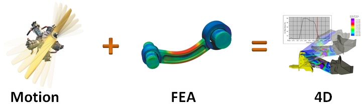
SimWise 4D es la combinación de SimWise Motion y SimWise FEA resultando un producto de simulación mecánica perfectamente integrado. SimWise 4D ofrece las mismas capacidades que de forma independiente ofrecen SimWise Motion y SimWise FEA pero la integración produce una capacidad conjunta de movimiento y FEA que permite calcular las tensiones resultantes de las cargas dinámicas inducidas por el movimiento de un ensamblaje.
SimWise Motion takes a design made up of assemblies of moving parts and simulates the kinematic and dynamic motion of the design allowing you to evaluate its function performance.
Creating the Motion Model
SimWise Motion lets you start with an assembly designed in your CAD system or one created using SimWise’s basic geometry creation capabilities. The physical properties of each of the parts in the assembly will be calculated and if assembly constraints were present in the CAD mode, they will be automatically converted to SimWise constraints.
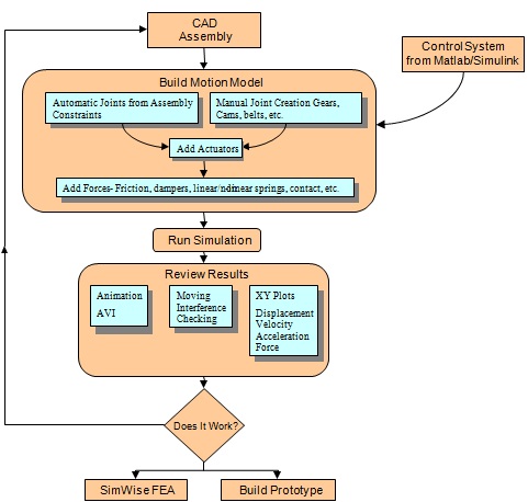
Adding/Controlling Motion
To make your simulation closely reflect real word functionality, SimWise Motion allows you to add various motion characteristics to your model. SimWise Motion supports motors, actuators, gravity, realistic contact between bodies, springs, friction, damping and other generated forces as needed.
Running the Simulation
Running a simulation is as simple as specifying how long you want the process to run and then clicking the calculator icon to compute your motion results.
Reviewing Results
SimWise Motion calculates several types of results that you can use to verify the operation of your design. Animations give you the visual feedback you need to understand if your design will work properly. However, what truly sets SimWise Motion apart from a general animation package is the ability to provide accurate, physics based, engineering data associated with the movement of the assembly. Result vectors and plots of displacement, velocity, acceleration and forces, give you the numerical information you need to fully understand the performance of your design. As you make design changes, you can compare the data to verify design improvement.
Does it Break?
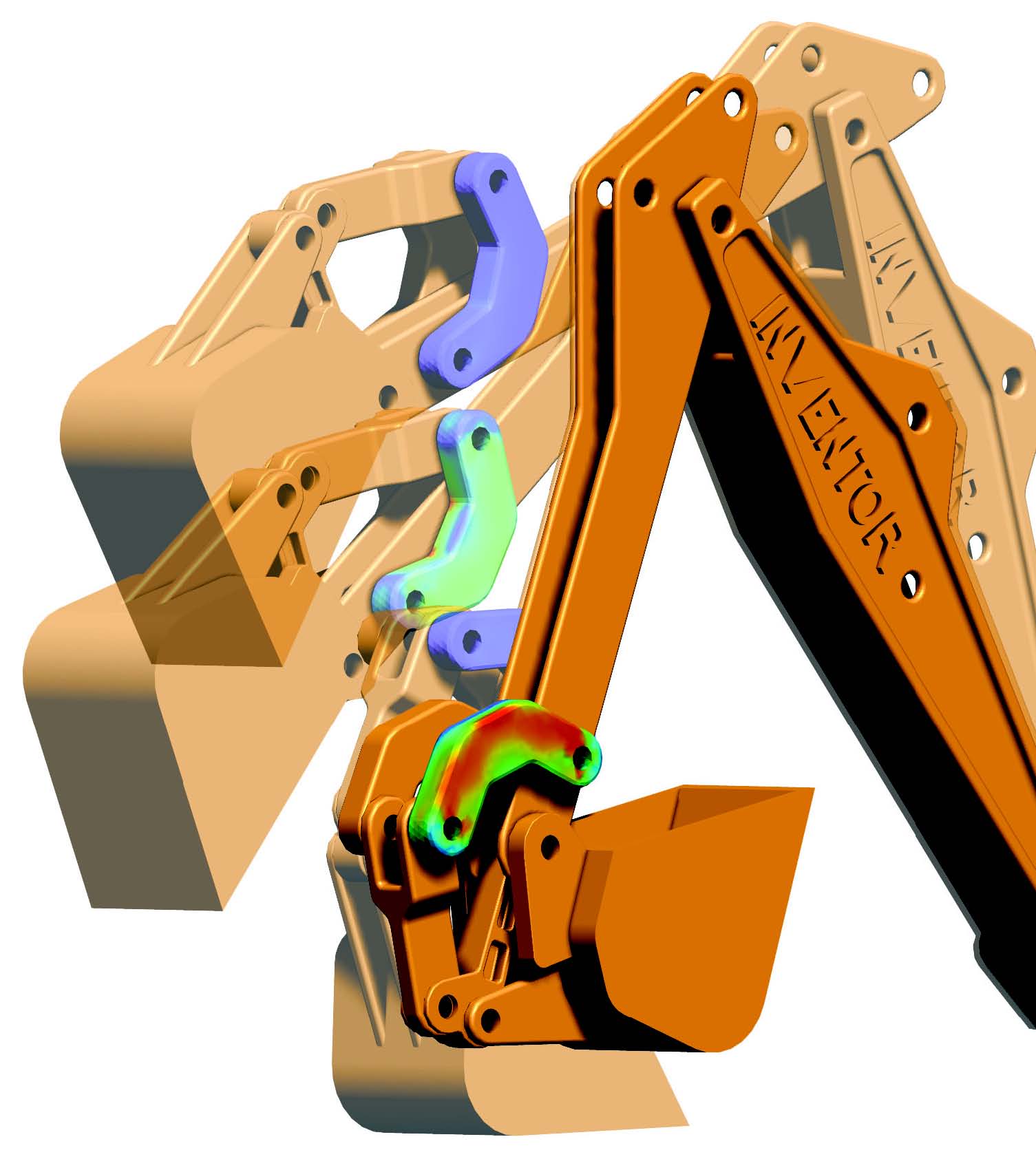
SimWise Motion helps you answer the question “Does my design work?”, but its real power is relaized when it is coupled with SimWise FEA. The reaction forces that were cacluated by SimWise Motion are automatically applied to an FEA model created by SimWise FEA so you can see the atresses that result from the movement of the assembly. Not only can you answer with confidence, “Does it Work?” you can also answer “Does it Break?”
SimWise FEA is a Finite Element Analysis tool that performs stress, normal modes, buckling, and heat transfer analysis on mechanical parts. It is highly automated and handles much of the complexity associated with FEA while offering powerful features for users who are steeped in the intricacies of the Finite Element Method.
It imports geometry from your CAD system and allows you to add structural and thermal specific entities to the model resulting in a functional structural prototype of your design. It simulates that prototype using advanced physics and mathematical techniques and presents the results of the simulation in various graphic and numeric formats. You can quickly determine whether your design is robust enough to operate as intended or if modifications are necessary. All on the computer, all without costly and time-consuming physical prototypes and before warranty issues arise.
Rich set of Loads and Restraints
SimWise FEA has a rich set of functional objects that are added to your CAD model to build a functional structural prototype. These objects include:
- Concentrated loads, distributed loads, torques, and pressures
- Restraints and enforced displacements
- Prescribed temperatures, conductive and convective heat flux, and radiation
All of these values can be driven by the SimWise formula language. All of these objects are applied to the underlying geometry, not to nodes and elements as in a traditional FEA product.
Solver Technology
SimWise uses a fast iterative Finite Element Analysis solver that takes advantage of multi-core processors and which is based on a Preconditioned Conjugate Gradient method. SimWise FEA exclusively uses ten-node tetrahedral elements and the solver is optimized for this type of problem.
SimWise FEA can display FEA results as shaded contours, deformed shapes, or animations. In addition to these engineering values, SimWise FEA also calculates factors of safety and errors in the stress results and both of these can be displayed as shaded contours.
Adaptivity means Confidence
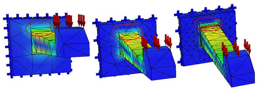 Adaptivity refines the FEA model in areas of high stress
The error results can be used to drive an iterative solution process called h-adaptivity where the error results are used to refine the Finite Element mesh in areas with large error values and use that new mesh to run another solution. The errors in the new solution are compared to a goal and if error values in the model still exceed the goal, the process is repeated with successive mesh refinements and analyses until the error goal is achieved. Confidence in the results are increased and no special knowledge about appropriate meshing techniques is required.
Durability Analysis and Fatigue Calculations
Fatigue damage is one the most common causes of structural failure, and can lead to disastrous outcomes. Therefore, prediction of structural fatigue life is essential in modern product design.
SimWise 4D already calculates the dynamics loads that result from the motion of a mechanism, and the stresses and strains that result from those dynamic loads. SimWise Durability uses the stresses and strains to compute the fatigue life.
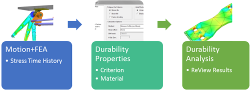
The schematic above shows the entire Durability process. After completing a Motion + FEA analysis, choose the the durability material properties and the fatigue life calculation method, run the durability solver, and review the results.
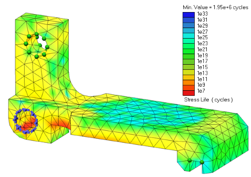
SimWise Durability is built on widely used fatigue calculation methods. It offers fatigue calculations based on stress life, strain life or factor of safety criteria. It comes with more than 150 materials with fatigue properties based on the SAE J1099 standard. It produces contour plots showin either the fatigue life in cycles, or the factor of safety.
SimWise Durability is an add-on to SimWise 4D and requires a license of SimWise 4D be present prior to its use.
Evaluation versions of SimWise 4D include an evaluation copy of SimWise Durability
See a video of SimWise Durability in action.
Once you know a design will work and is strong enough to operate safely, you can start to consider making trade-off between product attributes in the areas of weight, cost, manufacturability, and performance. SimWise 4D contains the HEEDS® optimization engine from Red Cedar Technology whichs rapidly iterates through many design alternatives looking for design parameters that meet all targets and criterias.
Three things are needed for optimization:
- Parameters – The values that will be changed to achieve an optimized objective. These can be any type of SimWise value, such as the stiffness of a spring, or the location of a joint.
- Objective – The value(s) to be optimized. Any SimWise quantity that can be displayed on a meter can be an objective.
- Constraints – Place bounds on the optimization. Any SimWise quantity that can be displayed on a meter can be used as a bound.
As the optimizaiton runs, the engine will choose different values for the parameters and run multiple Motion, FEA, or Motion+FEA simulations. The high performance search algorithms in the HEEDS® engine guide the choice of parameter values. The data from each run are preserved and can be reviewed. Each run is ranked in terms of how it meets the optimization criteria and the rankings can be used to arrive at the final values used for your design.
An example is show in the simple model:
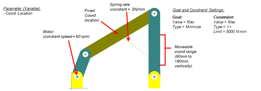
The goal is to determine the location of the spring end attachment such that the maximum torque on the motor is less than or equal to 5000 N-mm
The variable is the Y coordinate of the spring attachment point.
The objective is to minimize the maximum value of the motor torque.
The constraint is that the maximum value of the torque is less than or equal to 5,000 N-mm
The popular Simulink product from The MathWorks, Inc., makers of MATLAB®, integrates effortlessly with SimWise Motion. A pre-defined block (sWPlant) can be added into Simulink to represent the mechanical system in SimWise, allowing you to simulate an entire system, including hydraulics, electronics, and controls. Simulink output variables can be connected to SimWise Motion entities and SimWise motion output values connected to Simulink inputs creating a coupled simulation.
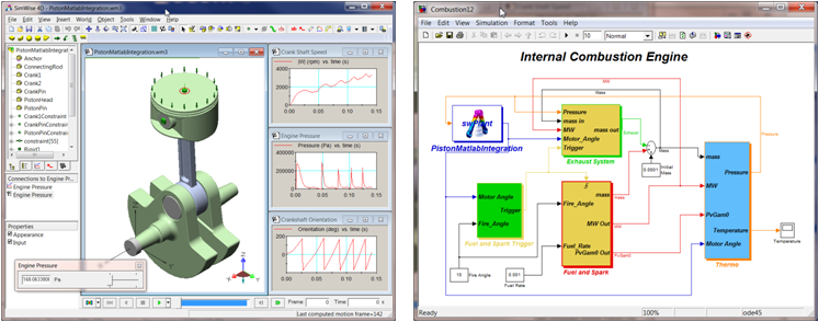 Simulink combustion model integrated with SimWise engine model
SimWise is CAD neutral but provides three methods of using CAD assemblies for motion and FEA simulation.
- CAD Plug-ins or Add-ons that transfer geometry and assembly constraints in an associative manner to SimWise. Changes to the CAD model are reflected in the SimWise model.
- Native File Readers that directly read the CAD system database and convert the assembly geometry to SimWise.
- Neutral file formats such as STEP, IGES, Parasolids (x_t and x_b), ACIS, and STL.
CAD Plug-ins
Plug-in or Add-ons are available for the following CAD systems:
SOLIDWORKS Solid Edge Autodesk Inventor SpaceClaim Geomagic Design The plug-in allows you to transfer a complete assembly model including constraints to SimWise with one click of a menu. During the transfer process associsativity links are built that connect the SimWise model to the CAD assembly. If a change is made to the CAD assembly it can be reexported to SimWise and only the changed portion of the model is updated in SimWise. Assembly constraints are mapped to SimWise constraints and where possible multiple lower order assembly constraints are converted to single higher order SimWise constraint.
Native File Readers
Assemblies can be read directly from the following CAD systems:
Catia V4 Catia V5 Unigraphics SolidWorks Solid Edge Inventor Creo/Elements Since data is only read from the CAD assembly file, constraints and associative links are not possible. A SimWise model created from one of the above CAD systems can be updated to reflect changes made to the CAD model after the initial transfer.
Neutral File Formats
The following neutral file formats are supported:
STEP IGES VDA-FS Parasolids ACIS